High Q Notch Filter Circuit Diagram
Problem with notch filter implementation Notch active electrical4u transfer Notch filter: the circuit’s diagram and the design formula – electronic
audio filter circuit : Audio Circuits :: Next.gr
Designing notch filter circuits ~ electronic circuit projects Notch filter (bandstop): what is it? (circuit & design) High q notch filter ~ circuitos de electronica
Band filter pass circuit notch stop electronics electrical
Filter notch uses operational circuit amplifier audio tunable simple diagram applications gr nextFilter circuit notch solved voltage diagram shown figure transcribed problem text been show Designing notch filter circuitsNotch filter circuits designing understood therefore must.
Notch tunable seekicCircuit electrinic: october 2013 Solved 3.2 the notch filter circuit for the circuits in fig.Twin t active notch filter.

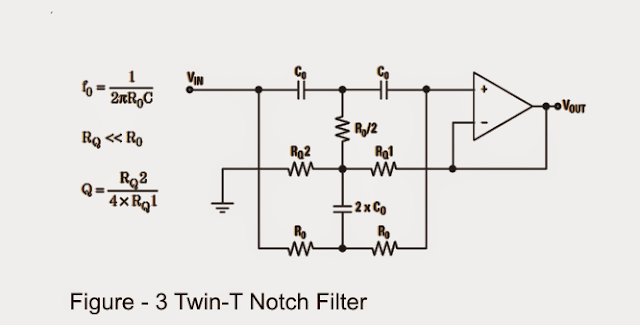
High-q notch filter with active twin t network
Notch filter theory electrical circuitNotch filter circuits with design details Circuit basic seekic tunable notch filterNotch soorten 9mhz configurations.
The circuit diagram of high q notch filterFilter audio notch circuit variable circuits filters gr next value double three consists substantially symmetrical capacitors resistors High q notch filter electronic competition module signal conditioningNotch filter circuit electronic projects.

Tl081 tunable notch filter ~ amplifiercircuits.com
Notch filter- theory, circuit design and applicationNotch filter implementation problem hz works Notch filter formula diagram circuit op amp 2008 eeg schematic november circuits arduinoSimple notch filter uses an operational amplifier.
Band pass and band stop (notch) filterCircuit filter diagram notch seekic control Solved in the notch filter circuit shown in the figure,The circuit below is an active notch filter with a.
Filter notch circuit laser diagram circuits tolerance hq without close opamps trimmed incorporating resistors special figure electrinic
Op ampCircuits hz Index pageFilter notch tl081 tunable circuit audio frequency band hum circuits narrow gr next.
Filter notch adjustable active pass low schemaSoorten auto's: maart 2014 Notch filter circuit theory application amp electrical single opFilter notch active circuit frequency rc response bw.
60hz notch filter
Filter notch twin active circuit network diagram schematic determined equation f0 followingNotch electronic signal frequency conditioning module competition filter custom high Hq notch filter without close-tolerance components circuit diagramAudio filter circuit : audio circuits :: next.gr.
Hq notch filter without close-tolerance components circuit diagramFilter notch twin active band stop reject narrow factor engineering electrical questions stack quality Notch filter- theory, circuit design and applicationTunable_notch.

Filter notch factor response lc frequency band active narrow removed signal path when elektronik beis
The circuit below is an active notch filter with aNotch filter- theory, circuit design and application Notch filter tolerance hq without close componentsSchematic reading help, please.
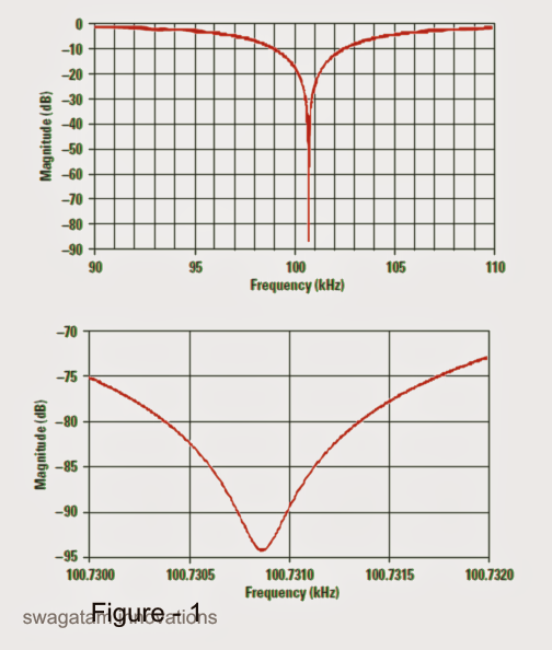
15 filter circuits using electronic coilHum filter circuit using electronic coil Filter electronic hum using circuit coil frequency circuits eleccircuit simple bc549 transistor divider massager figureNotch filter tolerance diagram circuits hq without close components resistors reach capacitors within deep figure using just circuit.

Notch filter circuit active help understanding please am
Circuit filter seekicNotch filter twin circuit active 60hz audio schematic 60 hz amp op network filters simulation circuits gr next simulator am Filter notch using 60hz lm741 eleccircuit hum bootstrapped.
.


